Degenerative Faceting
Options > ACIS > Degenerative Faceting
Degenerative Faceting is when the surfaces and edges of a 3D model are represented by degenerated facets composed of regular, uniform polygonal shapes. This reduces the surface lines on complex objects such that only their edges, surface lines and curves are displayed.
NOTE : Degenerative Faceting is frequently used for display purposes only as the reduced faceting lines can be misrepresented during modeling, rendering or analysis procedures.
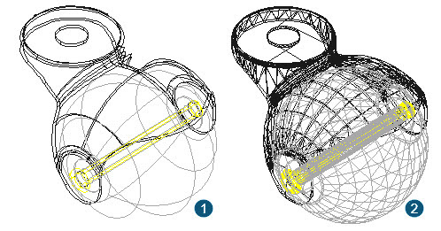
Activating the Degenerative Faceting option is particularly useful when designing and assembling spherical or cylindrical objects as demonstrated in the illustrations below.
Example 1 shows the Degenerative Faceting option activated.
Example 2 shows the Degenerative Faceting option deactivated.
Degenerative Faceting & Form Building Edges
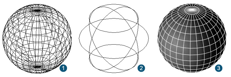
The Degenerative Faceting and Form Building Edges options have no impact on the Suppress Hidden Line, Draft or Quality rendered result, shown below.
Example 1 shows Form Building Edges and Degenerative Faceting activated.
Example 2 shows Form Building Edges activated and Degenerative Faceting deactivated.
Example 3 shows the rendered result with either option activated or deactivated.
Allow Axis Scale
This feature determines whether a 3-dimensional scale can be performed when resizing the part. This refers both to selector shell scaling and Inspector Bar input into the Scale X, Scale Y and Scale Z data fields.
- When Allow Axis Scale is deactivated, the selected part can only be scaled using the values of 2 axes.
- When Allow Axis Scale is activated, the selected part can be scaled using proportional scaling by inputting the values into the Scale X, Scale Y and Scale Z data fields.
Faceter Quality
The Faceter uses an anti-aliasing process which balances performance (speed) against the rendered result. This is done by examining the facet edges and pattern and calibrating the result based on whether the smoothing is done using an SMAA (Sub-pixel anti-aliasing process) or a FXAA (Fast Approximate Anti-Aliasing) process. The degree of the faceter quality determines the rendered outcome.
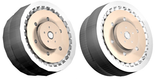
In the example below left, the faceter quality is set to 50% which produces a fast rendered result, but produces a higher degree of faceting on both the edges and the pattern quality.
In the example below right, the faceter quality is set to 100% which is computationally more demanding, but produces smoother edges on both the facet edges and the material pattern.
To adjust the faceter quality, navigate to Options > ACIS and adjust the faceter quality to correspond to the desired rendered result.
Create Editing History (Part Tree)
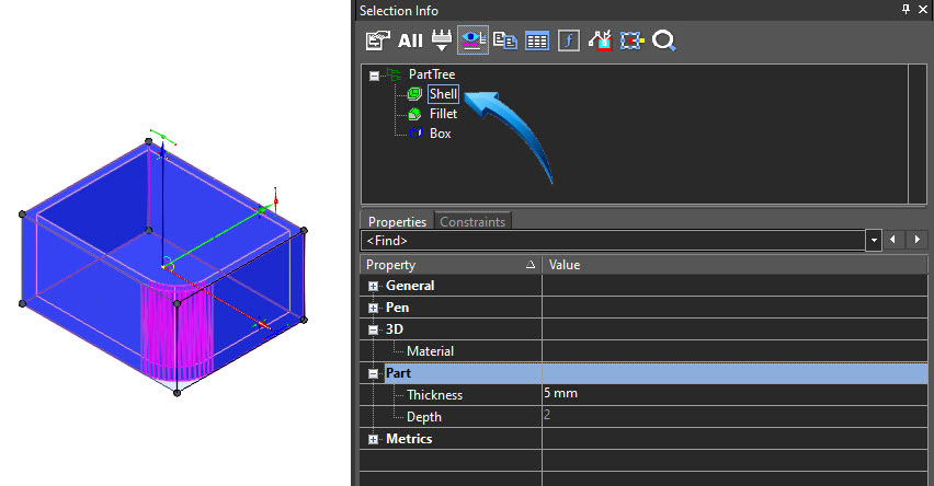
When this option is enabled, parts created in the editor are ordered into a Part Tree in the Selection Info palette.
This allows all properties of the individual parts to be modified at any stage of the design, even when boolean functions are performed.
Below is an example of the Part Tree history for a single part.
Creating a Part Tree History
Show Selected Axes for Solid Objects
An assembly of parts can be done by alignment and rotation, specifically when assembling the central axis of 2 cylindrical objects. To perform this assembly, an Axis must be visible.
By activating the Show Selected Axes for Solid Objects option in the ACIS settings, the axes for parts intended for assembly are visible, shown below.
In the example below, the assembly axes of the parts to be assembled are shown. This option is enabled using the Modify > Assemble > Set Assembly Axis option.
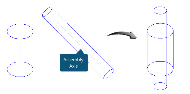
Assembly by Axis - Assembly Axes shown
See Also